
Creating Markers
To successfully estimate the camera pose (position and orientation in 3D space), the software requires a set of reference points on the screen surface model. These markers act as the bridge between the digital 3D model and the physical projection environment.
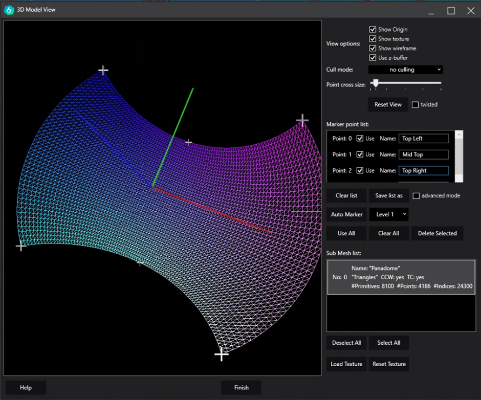
Requirement: A minimum of 6 markers is necessary for a successful camera pose estimation. Using more markers generally increases the accuracy and stability of the calculation.
Marker Point List and Basic Controls
Section titled “Marker Point List and Basic Controls”The Marker point list displays all active reference points on the model.
- Marker Entry: Each entry shows the marker index (e.g., Point 0), a Use checkbox to include/exclude it from the calculation, and a Name field for custom labeling.
- Advanced mode: Toggling this checkbox expands the list to display the specific 3D coordinates (X, Y, Z) for every marker.
- Use All / Clear All: Bulk commands to either enable all markers in the list or disable them simultaneously.
- Delete Selected: Removes the currently highlighted marker from the list.
- Clear list: Deletes all markers, resetting the list to empty.
Save list as: Exports the current marker set to a file for later use or for other projects using the same geometry.
Auto Marker Generation
Section titled “Auto Marker Generation” 
For simple geometries geometries markers can be generated automatically using the Auto Marker feature.
- Auto Marker Button: Triggers the automatic placement of points based on the mesh geometry.
- Level Selection: This dropdown determines the density of the generated points.
- Level 1: Generates 6 markers (the minimum required).
- Level 2: Generates 15 markers for higher precision.
- Higher Levels: Increases the marker count accordingly to ensure dense coverage across the entire surface.